


COMMUNICATION SYSTEMS
COMMUNICATION SYSTEM
The terms communication signifies
- transmission
- reception
- processing of information by electrical means
Some examples of communication system
- Telephony and telegraphy
- Mobile communication
- TV-broadcasting
- Radar
- Radio aids to navigation and aircraft
Basic constituents of communication system are
- Collation (sorting), processing and storage of information
- Actual transmission of information
- Reception of information involving decoding, storage and interpretation
BASIC BLOCK DIAGRAM OF A COMMUNICATION SYSTEM
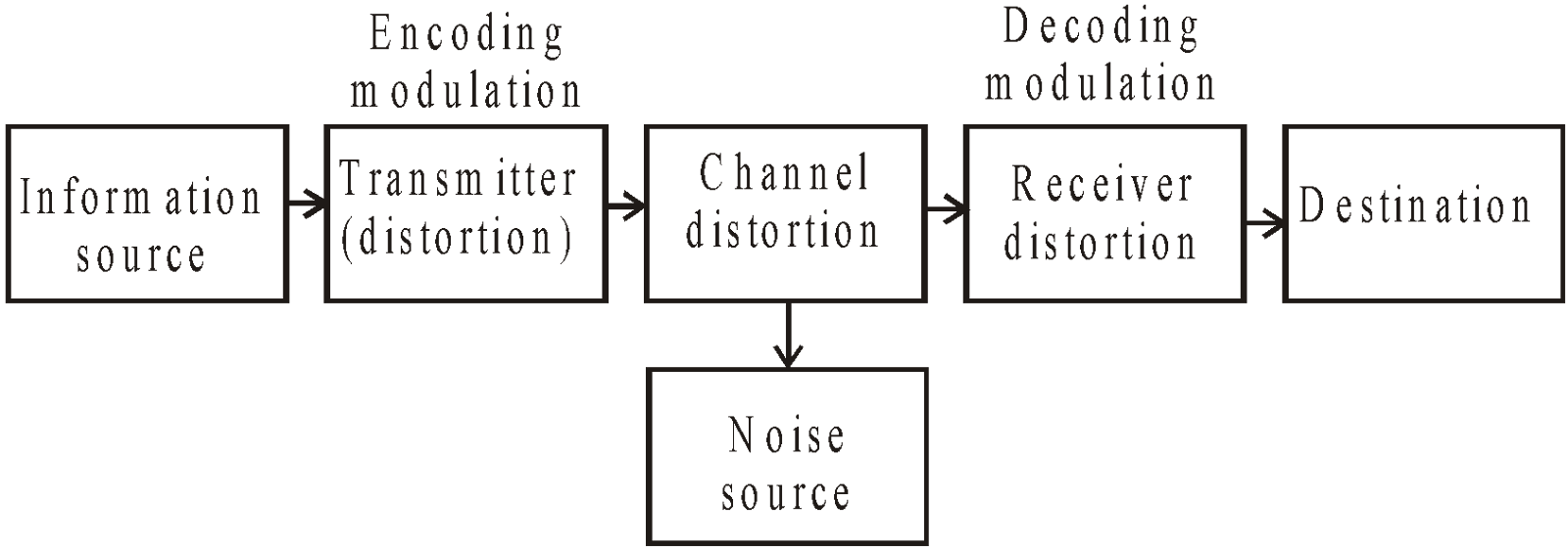
- Information source : A communication system serves to communicate a message or information. Messages are in form of words, group of words, code, symbols etc. Out of these messages, only the desired message known as information is selected and conveyed in form of bits or digits.
- Transmitter : A high or low level broadcast transmitter can be take in use as per the requirement.
BLOCK DIAGRAM OF HIGH LEVEL BROADCAST TRANSMITTER
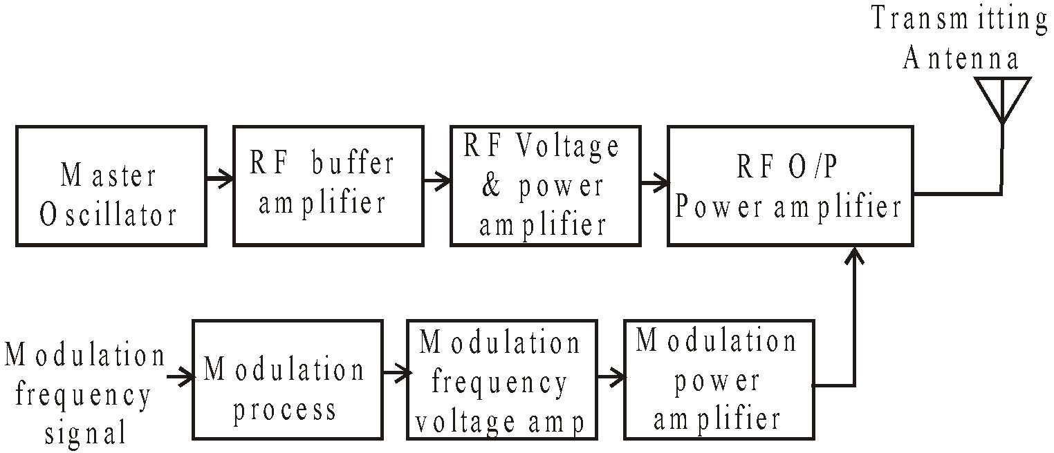
BASIC FUNCTION OF EACH BLOCK
- Transducer : converts the information into electrical signal.
- Modulation processing stage : compressed and limit the audio frequency in amplitude range.
- Modulation frequency voltage and Power amplifier : for amplification purpose.
- Master oscillator : generates stable carrier voltage of desired frequency.
- RF buffer amplifier : isolate master oscillator from influence of modulation done at later stage.
- RF voltage and power amplifier : Carrier gets amplitude modulated
- Transmitting antenna : radiate information in form of e.m. waves.
- Channel and noise source : Channel in the medium through which message travels from the transmitter to the receiver. Noise source may get added to signal at any point in the communication system.
- Receiver : They may be of widely different varieties. The simplest radio receiver is the crystal receiver having one semiconductor crystal and headphone.
BLOCK DIAGRAM OF SUPERHETERODYNE RECEIVER
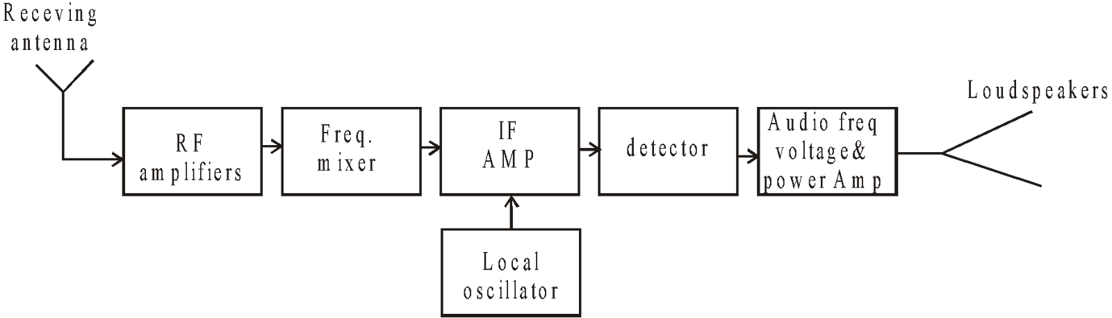
BASIC FUNCTION OF EACH BLOCK
- RF amplifier : amplifies weak RF signal
- Local oscillator : generates frequency to get IF at later stage.
- Mixer : mixes RF signal with local oscillator–o/p. thereby producing IF
- IF amplifier : amplifies IF signal.
- Detector : demodulates original signal
- Audio frequency voltage & power amplifier : amplifies signals
- Loudspeaker : reproduce original sound signal.
KEEP IN MEMORY
- There are two basic modes of communication :
- Point to point mode : It is when single receiver correspond to a single transmitter e.g. telephony.
- Broadcast mode : It is when number of receiver correspond to a single transmitter e.g. radio and television.
- Signal is the information converted in electrical form and suitable for transmission.
- Analog signal : It is the continuous variations of voltage or current.
- Digital signal : It can take only discrete stepwise values. 'O' correspond to a low level of voltage or current and 1 correspond to a high level of voltage or current.
- Attenuation : It is the loss of strength of a signal while propagating through a medium.
PROPAGATION OF ELECTROMAGNETIC WAVES IN ATMOSPHERE
- Radio waves also known as electromagnetic waves which when radiated from transmitting antenna, travel through space to distant places where they are picked up by receiving antenna .
- These waves are unaffected by the atmospheric pressure, rain, snow etc.
- They can cross the non-metallic objects but are highly attenuated by the metals.
- These waves travel with a speed of light 3 × 10⁸ m/s in vacuum.
- They do not require any material medium for their propagation.
- On the basis of different behaviour of atmosphere of radio waves of different wavelengths, there are the following three modes of propagation of radio waves.
- Ground or surface wave propagation
- Space or tropospheric wave propagation
- Sky or ionospheric wave propagation
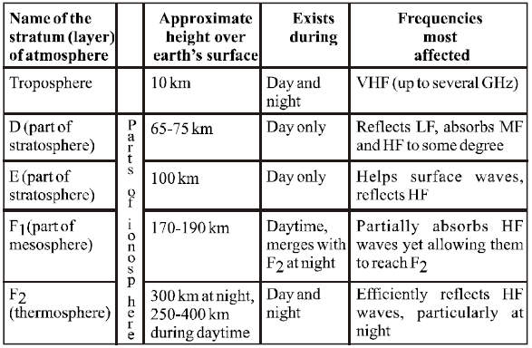
Different layers of atmosphere and their interaction with the propagating electromagnetic waves
SURFACE WAVE PROPAGATION
In this mode, the radio waves are directed by the earth and they travel along the curved surface of earth from the transmitter to the receiver.
- Surface wave propagations are of two types.
- Short – distance surface wave propagation
- Long – distance surface wave propagation.
- When the distance between the transmitting and receiving antenna is short the field strength for surface wave propagation for a flat surface is
...(1)
EO : the unit distance field strength at the surface of earth.
d : the distance from transmitting to receiving antenna
A : the factor taking into account losses caused by the earth.
- The above equation (1) is applicable for distance upto
(f = frequency in MHz).
- Distance
equation (1) has to be modified to take into account curvature of earth.
- For long distance propagation reduction in field strength is due to curvature of earth.
- Surface wave propagation is marked as wave A in figure (1).
KEEP IN MEMORY
Surface wave propagation is possible for frequencies upto 500 kHz, that can propagate upto a distance of 1500 km because attenuation of ground waves increases with increase in frequency of waves.
For local region propagation upto 15 MHz frequency is possible.
SPACE WAVE PROPAGATION
Also known as tropospheric propagation find its wide scope at frequencies like V.H.F, U.H.F and microwaves.
In this mode, the radio waves are transmitted from the transmitting antenna at a small angle with the earth's surface, which reaches the receiving antenna in following three ways:
- Some part of the transmitted waves get reflected by troposphere and reach the receiving antenna (shown as wave B in fig (1) .
- Some part of the radio waves reaches directly to the receiving antenna (shown as wave C in fig (1)
- Some part reaches after reflection from the earth's surface (shown as wave D in fig (1))
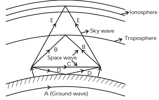
Fig (1) : Modes of Propagation of radio waves.
When e.m. wave passes through the ionosphere, the electric – component of waves exerts a force on the electrons and thus electrons starts oscillating along path parallel to electric field of wave.
Let electric field across m3 of space in ionosphere be E = Em sinωt
Force on each e– is F = – qe newton
Instantaneous velocity of e– is
∴ Instantaneous electric current by N electrons is
ie = – qN v and capacitive current is ic
ie = – qN v and capacitive current is ic
Total current i = ie + ic = 
The effective value of dielectric constant 
or 
Note:-
- ie lags behind electric field by 90°
ic leads electric field by 90°. - The reduction in the value of ∈ causes bending of path of radio waves.
Substituting ∈0 = 8.854 × 10⁻¹² farad/m
e = 1.6 × 10 –19 coulomb
m = 9.1 × 10 –31 kg
Then 
The refractive index of ionised medium

For n < 1 the ionised medium behaves as raw medium, so waves entering the medium deviates away from straight path.
If  is angle of incidence,
  angle of refraction, then
 .
.
For T.I.R 
For 
 or
or 
This frequency fc is the critical frequency of e.m. wave which is max-frequency for which the wave gets reflected back.
KEEP IN MEMORY
- During night F1 and F2 layers merge to form one single layer-F2 due to this, propagation of radio waves gets affected/varies from day to night.
- As the angle of incidence φi is reduced, the distance from transmitting to receiving point decreases to a minimum and then again increase. The minimum distance from the transmitter at which sky wave of given frequency is returned to earth by ionosphere is known as skip-distance.
- If h is the height of antenna then the distance covered by transmission
where R = 6.4 × 10⁶ m is the radius of the earth.
If the transmitting and receiving antennas are placed at heights Ht and Hr , the maximum range of space wave communication is
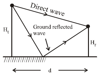
Fig (2) : Direct and ground reflected wave of space wave.
For calculation of distance between the transmitting and receiving antenna, equation (2) is further modified as
considering that the space wave propagate along straight path and the earth’s effective radius is 4/3 times the actual radius.
SKY-WAVE PROPAGATION
Also known as ionospheric propagation are used for long-distance radio communication.
- In this type of propagation, the energy content of the wave reaches the receiving antenna as a result of bending of path due to ionization in the upper atmospheric layer (ionosphere).
- The ionization in the ionosphere is not uniform but it is stratified, i.e. in the form of layers. The layers are designed as D, E, F and F2 layer.
MODULATION AND ITS NEEDS
For long range transmission of audio frequency e.m.waves, before transmission are superposed with radio frequency waves. The process of superposition of audio frequency waves with radio frequency waves is called modulation.
During the process of modulation
- the audio frequency wave that needs to be transmitted is known as modulating wave
- the radio frequency wave superimposed on it is known as carrier wave
- the resultant wave obtained due to superimposition is called modulated wave
Modulation of audio frequency waves are done because of the following two reasons :
- The energy content of these waves is quite low and therefore due to attenuation while travelling over a long distance their amplitude is greatly reduced.
- The length of antenna required for the transmission must be of order of the wavelength of waves to be transmitted is very larger around 104 m, which is practically not possible.
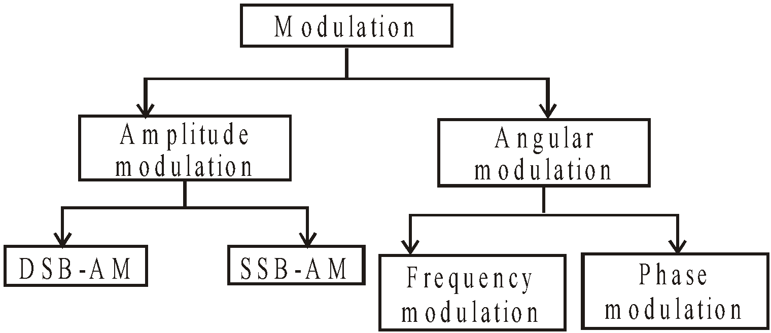
Modulation is Done in Two Ways
- By changing amplitude of carrier wave
- By changing total phase of carrier waves
By the process of modulation, the properties of high frequency carrier wave like amplitude, frequency, phase etc are changed corresponding to the instantaneous value of low frequency audio waves.
AMPLITUDE MODULATION (AM)
Amplitude modulation is the process in which one modulating wave of low frequency are superposed with carrier waves of high frequency such that the amplitude of carrier waves changes in accordance with the amplitude of modulating waves.
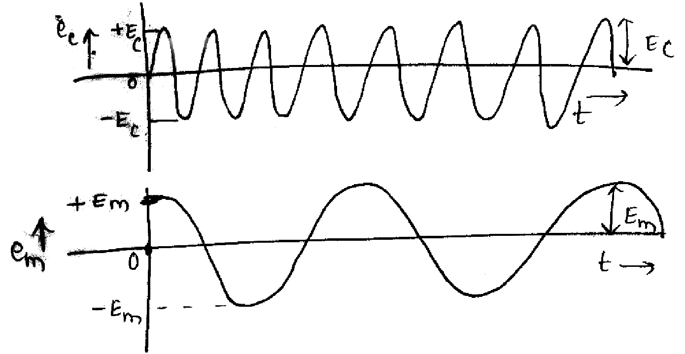
Let, modulating signal be em = Em cosωmt
carrier signal be ec = Ec cos ωct
ωm<<ωc(angular frequency)
Modulated signal (e)AM = [Ec + ka Emcosωmt] cosωct
= 
= Ec[1 +macosωmt]cosωct
DEPTH OF MODULATION

Greater the value of ma, more clear and intense is the superposition of modulating wave over the carrier.
modulation,
then KaEm  i.e. max-variation of amplitude of carrier wave is half the amplitude of unmodulated carrier wave.

- ma =1 ⇒ 100% modulation then KaEm = Ec , i.e. when the modulating wave has maximum +ve amplitude, the amplitude of modulated wave is twice the amplitude of carrier wave.
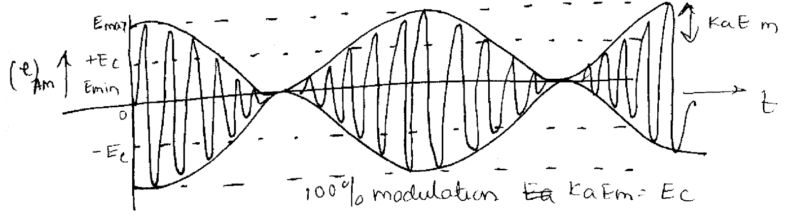
when one modulating wave has maximum-ve amplitude the amplitude of modulated wave is zero.
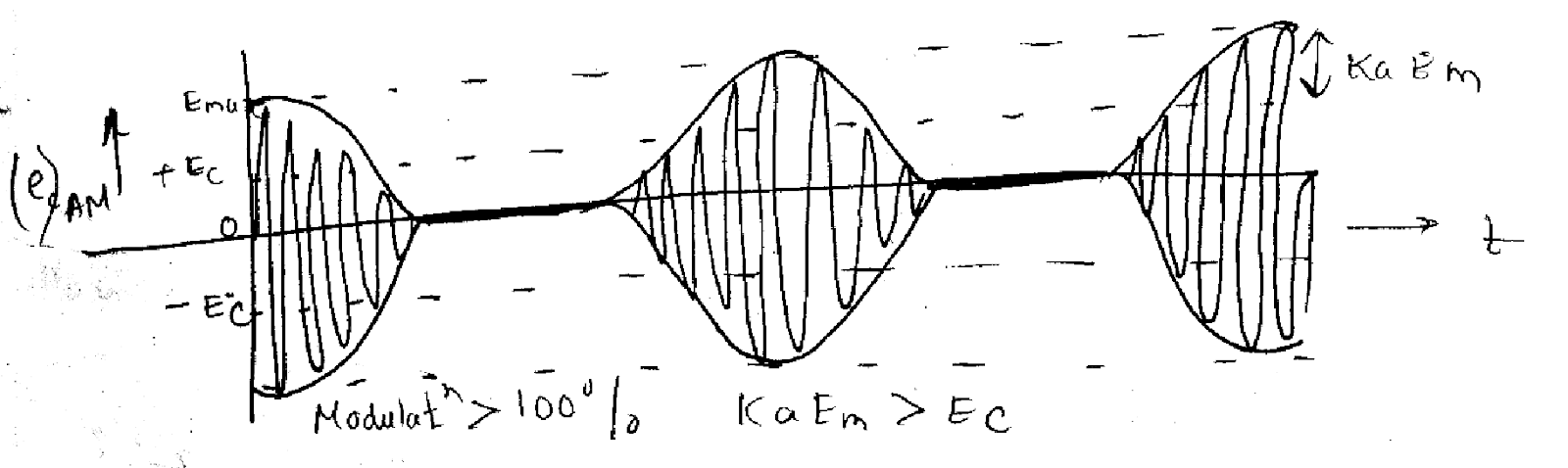
- ma >1⇒ modulation is greater than 100% then kaEm > Ec. In this condition amplitude of modulated wave remains zero in some part of modulating wave, as a consequence there is distortion which is undesirable.
AM FREQUENCY SPECTRUM
Since (e) AM = Ec( 1 + ma cosωmt) cosωct
⇒ (e)AM = Ec cosωct + Ecma cosωmt cosωct
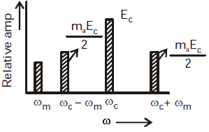
The above expression shows that AM-wave comprises of following there frequencies :
- Carrier wave of frequency ωc and amplitude EC
- Wave of frequency (ωc + ωm) and amplitude
- Wave of frequency (ωc – ωm) and amplitude
- Frequency (ωc + ωm) is the upper side band frequency.
- Frequency (ωc – ωm) is the lower side band frequency.
CAUTION
Please take into consideration that the audio signal is inherent only in the side frequency spectrum and it does not lie in the carrier frequency component.
METHODS OF AM
AM can be done by the following two methods :
- Linear modulation : This method uses linear portion of characteristics of tube or transistor.
- Square law modulation : This method uses non-linear portion of characteristics of tube/transistor.
KEEP IN MEMORY
- Carrier wave
frequency : ωc
amplitude : Ec,
r.m.s. value : - Lower side wave frequency
frequency : ωc – ωm
amplitude :
r.m.s. value : - Upper side wave frequency
frequency : ωc +ωm
amplitude :
r.m.s. value : - Power consumed by carrier wave :
- Power consumed by lower frequency wave :
- Power consumed by upper frequency wave :
- Total power consumed by side-frequency
PS F = PLSF + PUSF = 
If ma = 0 then PSF = 0
ma = 0.5 then PSF = 0.11P
ma = 1.0 then PSF = 0.33 P
To avoid wastage of power carrier voltage which contain maximum power is suppressed while modulation process as it does not contain any desired information. Similarly one of the side bands can also be suppressed so as to avoid wastage of power because each side- band carry the same desired information.
FREQUENCY MODULATION (FM)
In this type of modulation the frequency of the carrier voltage is varied in accordance with the instantaneous value of the modulating voltage.
Let modulating signal em = Em cosωmt
Carrier signal ec = Ec sin (ωc t + θ)
∴ Modulated signal
or (e)FM= Ec sin (ωc t + mf sinωm t).
mf is known as the modulation index/depth of modulation
The ratio of frequency deviation to modulation frequency is known as δ.

The total variation in frequency from the lowest to the highest is called carrier swing (CS)
CS = 2 × frequency deviation
⇒ CS = 2 × δ
KEEP IN MEMORY
- For commercial FM- transmission, maximum frequency deviation allowed is 75 kHz
- FM channel width is 2 × 75 = 150 kHz.
- In FM, the highest audio frequency transmitted is 15kHz
- Percentage modulation of FM is the ratio of actual frequency deviation to maximum allowed frequency-deviation.
i.e. For 100% modulation δactual = δ max.
MERITS OF FM
- There is a large decrease in noise
- S/N ratio is appreciable
- In FM, frequency allocation allows for a guard-band which helps in reducing adjacent channel interference
- FM permits use of several independent transmitters in the same frequency.
- The amplitude of FM-modulated wave remains unaffected.
DEMERITS OF FM
- Transmitting and receiving equipments are complex & costly
- Reception using conventional method is limited to line of sight.
- A much wider channel of 200 kHz is required.
APPLICATION OF FM TRANSMISSION
- FM broadcast band 88- 108 MHz with 200 kHz channels in which commercial FM station broadcasts audio signals.
- Sound signal in TV-broadcast is frequency modulator.
- FM is used in mobile & emergency services in the frequency range 20-4000 Hz.
- FM is also used in amateur band where only voice frequencies are transmitted.
SIDE-BAND AND BANDWIDTH
In actual practice the modulating signal (i.e. audio signal is not perfectly sinusoidal, but consists of various nearly frequency signal, on either side of carrier wave, use a pair of side frequency (ωc – ωm) and (ωc + ωm). These groups of side frequencies are called side bands.
- The group on higher frequency side of the carrier is called higher sideband.
- The group on lower frequency side of the carrier is called lower side band.
AM-SIDEBANDS
- Lower frequency band of AM signal = (ωc – ωm)
- Higher frequency band of AM signal = (ωc + ωm)
- (Angular bandwidth)AM = (ωc + ωm) – (ωc – ωm)= (2ωm)max
- (Bandwidth)AM or channel width
Let modulating signal be of 5 kHz , carrier signal of 1 MHz
∴ Side-frequency components are
LSF = 1 MHz – 5 kHz = 995 kHz
USF =1 MHz + 5 kHz= 1005 kHz
∴ Channel width = 1005 – 995 = 10 kHz
AM-SIDEBAND TRANSMISSION
It is found that it is not necessary to transmit all the signals one carrier and two sidebands) to enable the receiver to reconstruct the original signal.
Suppression of carrier and sidebands may be done by two process :
- DSB-SC (double sideband suppressed carrier system)
- SSB-SC (single sideband suppressed carrier system)
Former suppressed only the carrier while later suppresses one of the sideband and the carrier.
MERITS OF SSB-SC
- Bandwidth requirement is reduced by half so twice as many channels can be multiplexed in a given frequency range
- The size of power supply required is very small
- Since no carrier is transmitted so there is the possibility of interference
- SSB system eliminates the possibility of distortion.
- It provides an improvement to S/N of at least 9 dbs
DEMERITS OF SSB-SC
Transmitter and receiver become more complex.
APPLICATION OF SSB-SYSTEM
- Police wireless communication
- SSB telegraph system
- Point to point radio telephone communication
- V.H.F. and V.H.F. communication.
GENERATION OF SSB SYSTEM
- Filter method
- Phase cancellation method
FM-SIDE BAND
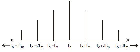
The frequency components of FM wave are :
ωo/fo
ωo± ωm / f0 ± fm
ωo ± 2ωm / fo ± 2fm
ωo ± 3ωm / fo ± 3fm and so on.
Bandwidth occupied by spectrum; BW = 2n fm.
n is the highest order of the significant sideband.
BW occupied by spectrum = 2(mf + 1)fm = 2(Δf + fm)
The above expression requires that mf > 6 i.e. the side bands of amplitudes < 5% of unmodulated carrier is negligible.
FM FREQUENCY SPECTRUM
KEEP IN MEMORY
- No. of side band of FM signal is proportional to amplitude of modulating signal
- No. of side band of FM signal is proportional to 1/frequency of modulating signal
i.e. pair of sidebands - increase as frequency deviation increase
- increase as modulating signal frequency decrease
Study Notes for JEE Main/JEE Advanced


Study Notes for NEET/AIIMS


