


WAVE OPTICS
WAVEFRONT
The locus of all particles of the medium vibrating in the same phase at a given instant is called a wavefront.
Depending on the shape of source of light, wavefront can be of three types.
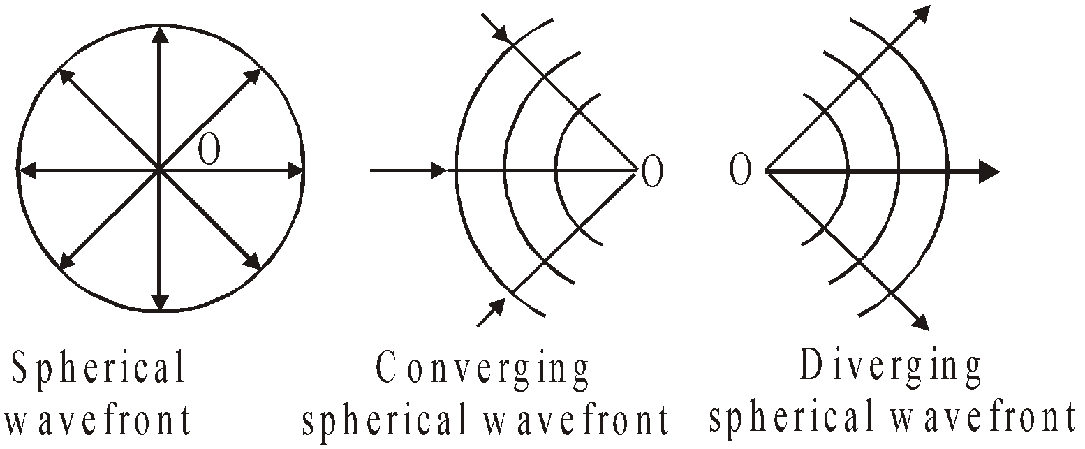
- Spherical wavefront : A spherical wavefront is produced by a point source of light. This is because the locus of all such points which are equidistant from the point source will be a sphere. Spherical wavefronts are further divided into two headings: (i) converging spherical and (ii) diverging spherical wavefront.
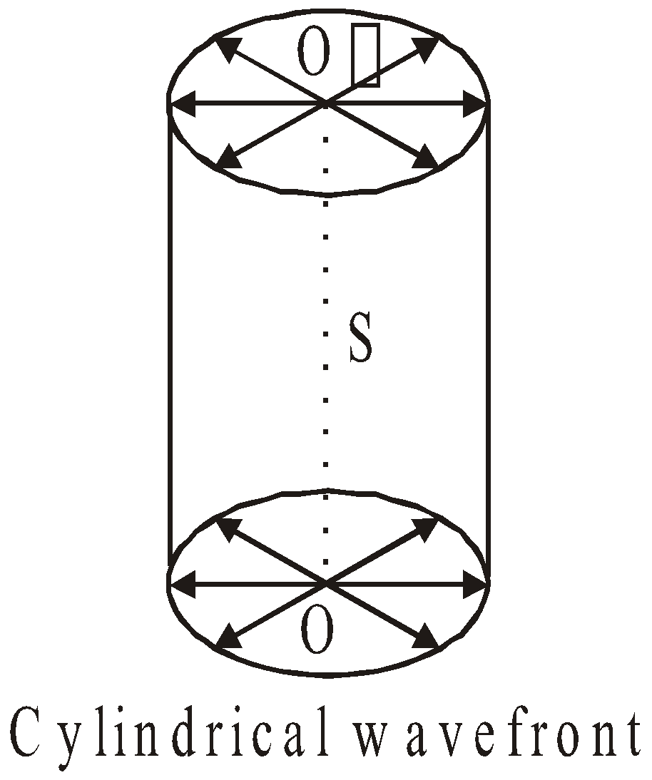
- Cylindrical wavefront : When the source of light is linear in shape such as a slit, the cylindrical wavefront is produced. This is because all the points equidistant from a line source lie on the surface of a cylinder.
- Plane wavefront : A small part of a spherical or cylindrical wavefront due to a distant source will appear plane and hence it is called plane wave-front. The wavefront of parallel rays is a plane wavefront.

HUYGENS WAVE THEORY
(Geometrical method to find the secondary wavefront)
- Each point source of light is a centre of disturbance from which waves spread in all directions.
- Each point on primary wavelets acts as a new source of disturbance and produces secondary wavelets which travel in space with the speed of light.
- The forward envelope of the secondary wavelets at any instant gives the new wavefront.


- In a homogeneous medium the wavefront is always perpendicular to the direction of wave propagation.
Note:- With the help of Huygen’s wave theory, law of reflection and refraction, total internal reflection and dispersion can be explained easily. This theory also explain interference, diffraction and polarization successfully.
DRAWBACKS OF HUYGENS WAVE THEORY
- This theory cannot explain photoelectric effect, Compton, and Raman effect.
- Hypothetical medium in vacuum is not true imagination.
- The theory predicted the presence of back wave, which proved to be failure.
REFLECTION AND REFRACTION OF PLANE WAVES USING HUYGENS PRINCIPLE
REFLECTION ON THE BASIS OF WAVE THEORY
According to Huygens principle, every point on AB is a source of secondary wavelets. Let the secondary wavelets from B strike reflecting surface M1M2 at A′ in t seconds.
∴  … (i)
… (i)
where c is the velocity of light in the medium.

The secondary wavelets from A will travel the same distance c × t in the same time. Therefore, with A as centre and c × t as radius, draw an arc B′, so that
AB′ = c × t … (ii)
A′B′ is the true reflected wavefront.
angle of incidence, i = 
and angle of reflection, r = 
In Δs AA′B and AA′B′,
AA′ is common,  and
and 
∴ Δs are congruent ∴  … (iii)
which is the first law of reflection.
Further, the incident wavefront AB, the reflecting surface M1M2 and the reflected wavefront A′B′ are all perpendicular to the plane of the paper. Therefore, incident ray, normal to the mirror M1M2 and reflected ray all lie in the plane of the paper. This is second law of reflection.
REFRACTION ON THE BASIS OF WAVE THEORY
XY is a plane surface that separates a denser medium of refractive index µ from a rarer medium. If c1 is velocity of light in rarer medium and c2 is velocity of light in denser medium, then by definition.
µ =  … (iv)

AB is a plane wave front incident on XY at  =
=  . 1, 2, 3 are the corresponding incident rays normal to AB.
According to Huygens principle, every point on AB is a source of secondary wavelets. Let the secondary wavelets from B strike XY at A′ in t seconds.
∴ BA′ = c1 × t … (v)
The secondary wavelets from A travel in the denser medium with a velocity c2 and would cover a distance (c2 × t) in t seconds. A′B′ is the true refracted wavefront. Let r be the angle of refraction. As angle of refraction is equal to the angle which the refracted plane wavefront A′B′ makes with the refracting surface AA′, therefore, .
Let , angle of refraction.
In ΔAA′B, 
In Δ AA′B′, 
∴  [using (iv)]
Hence  … (vi)
which proves Snell’s law of refraction.
It is clear from fig. that the incident rays, normal to the interface XY and refracted rays, all lie in the same plane (i.e., in the plane of the paper). This is the second law of refraction.
Hence laws of refraction are established on the basis of wave theory.
KEEP IN MEMORY
- In 1873, Maxwell showed that light is an electromagnetic wave i.e. it propagates as transverse non-mechanical wave at speed c in free space given by
- There are some phenomenon of light like photoelectric effect, Compton effect, Raman effect etc. which can be explained only on the basis of particle nature of light.
- Light shows the dual nature i.e. particle as well as wave nature of light. But the wave nature and particle nature both cannot be possible simultaneously.
- Interference and diffraction are the two phenomena that can be explained only on the basis of wave nature of light.
INTERFERENCE OF LIGHT WAVES AND YOUNG'S DOUBLE SLIT EXPERIMENT
The phenomenon of redistribution of light energy in a medium on account of superposition of light waves from two coherent sources is called interference of light waves.
Young performed the experiment by taking two coherent sources of light. Two source of light waves are said to be coherent if the initial phase difference between the waves emitted by the source remains constant with time.
The rays of light from two coherent sources S1 and S2 superpose each other on the screen forming alternately maxima and minima (constructive and destructive interference).
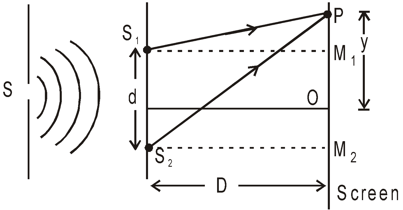
Let the equation of waves travelling from are
where A1 & A2 are amplitudes of waves starting from S1 & S2 respectively. These two waves arrive at P by traversing different distances S2P & S1P. Hence they are superimposed with a phase difference (at point P) given by
 ....(3)
where  (from fig) =
Similarly, 
so,  ....(4)
(A) CONDITIONS FOR MAXIMUM & MINIMUM INTENSITY
CONDITIONS FOR MAXIMUM INTENSITY OR CONSTRUCTIVE INTERFERENCE
If phase difference
δ = 0, 2π, 4π – – – 2nπ
or, path difference 
then resultant intensity at point P due two waves emanating from S1 & S2 is
or 
or  ....(5)
It means that resultant intensity is greater than the sum of individual intensity ( where A is the amplitude of resultant wave at point P).
CONDITIONS FOR MINIMUM INTENSITY OR DESTRUCTIVE INTERFERENCE
If phase difference,
or, path difference
then resultant intensity at point P is
or 
or  ...(6)
It means that resultant intensity I is less than the sum of individual intensities. Now as the position of point P on the screen changes, then the path difference at point P due to these two waves also changes & intensity alternately becomes maximum or minimum. These bright fringes (max. intensity) & dark fringes (min. intensity) make an interference pattern.
It must be clear that there is no loss of energy (at dark fringe) & no gain of energy (at bright fringe), but only there is a redistribution of energy.
The shape of fringe obtained on the screen is approximately linear.
(B) POSITION OF FRINGE
If Δ = S2P – S1P = nλ, then we obtain bright fringes at point P on the screen and it corresponds to constructive interference. So from equation (4) the position of nth bright fringe
or  ...(7)
(Position of nth bright fringe)
If , then we obtain dark fringe at point P on the screen and corresponds to destructive interference. So from equation (4), the position of, nth dark fringe is
or  ...(8)
(Position of nth dark fringe)
(C) SPACING OR FRINGE WIDTH
Let yn and yn+1 are the distance of nth and (n+1)th bright fringe from point O then
So spacing β between nth and (n+1)th bright fringe is
Since it is independent of n, so fringe width or spacing between any two consecutive bright fringes is same.
Similarly the fringe width between any two consecutive dark fringes is
(D) CONDITIONS FOR SUSTAINED INTERFERENCE
- The two sources should be coherent i.e. they should have a constant phase difference between them.
- The two sources should give light of same frequency (or wavelength).
- If the interfering waves are polarized, then they must be in same state of polarization.
(E) CONDITIONS FOR GOOD OBSERVATION OF FRINGE
- The distance between two sources i.e. d should be small.
- The distance of screen D from the sources should be quite large.
- The two interfering wavefronts must intersect at a very small angle.
(F) CONDITIONS FOR GOOD CONTRAST OF FRINGE
- Sources must be monochromatic i.e. they emit waves of single wavelength.
- The amplitude of two interfering waves should be equal or nearly equal.
- Both sources must be narrow.
- As Intensity I is directly proportional to the square of amplitude, hence Intensity of resultant wave at P,
If I1 = I2 = I0, then Imax = 4I0
- Angular fringe-width
- The width of all interference fringes are same. Since fringe width β is proportional to λ, hence fringes with red light are wider than those for blue light.
- If the interference experiment is performed in a medium of refractive index μ instead of air, the wavelength of light will change from λ to
.

i.e. 
- If a transparent sheet of refractive index μ and thickness t is introduced in one of the paths of interfering waves, then due to its presence optical path will become μt instead of t. Due to this a given fringe from present position shifts to a new position. So the lateral shift of the fringe,
- In Young’s double slit experiment (coherent sources in phase): Central fringe is a bright fringe. It is on the perpendicular bisector of coherent sources. Central fringe position is at a place where two waves having equal phase superpose.
- Young’s experiment with the white light will give white central fringe flanked on either side by coloured bands.
COHERENCE
The phase relationship between two light waves can vary from time to time and from point to point in space. The property of definite phase relationship is called coherence.
TEMPORAL COHERENCE
A light wave (photon) is produced when an excited atom goes to the ground state and emits light.
- The duration of this transition is about 10–9 to 10–10 sec. Thus the emitted wave remains sinusoidal for this much time. This time is known as coherence time (
).
- Definite phase relationship is maintained for a length
called coherence length.
For neon  ,
,  and L = 0.03 m.
For cadmium  ,
,  and L = 0.3 m
For Laser sec  and L = 3 km.
- The spectral lines width
is related to coherence length L and coherence time τc.
SPATIAL COHERENCE
Two points in space are said to be spatially coherence if the waves reaching there maintains a constant phase difference. Points P and Q are at the same distance from S, they will always be having the same phase.
Points P and P′ will be spatially coherent if the distance between P and P′ is much less than the coherence length i.e. 

METHODS OF OBTAINING COHERENT SOURCES
Two coherent sources are produced from a single source of light by two methods :
- By division of wavefront
- By division of amplitude.
DIVISION OF WAVEFRONT
The wavefront emitted by a narrow source is divided in two parts by reflection, refraction or diffraction. The coherent sources so obtained are imaginary. Example : Fresnel’s biprism, Llyod’s mirror, Young’s double slit, etc.
DIVISION OF AMPLITUDE
In this arrangement light wave is partly reflected (50%) and partly transmitted (50%) to produced two light rays. The amplitude of wave emitted by an extended source of light is divided in two parts by partial reflection and partial refraction. The coherent sources obtained are real and are obtained in Newton’s rings, Michelson’s interferometer, etc.
INCOHERENCE OF TWO CONVENTIONAL LIGHT SOURCES
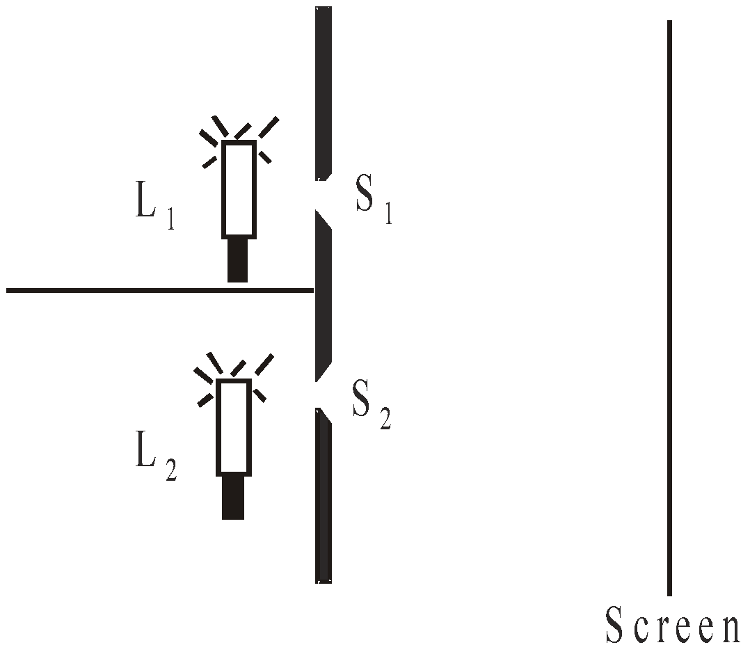
Let two conventional light sources L1 and L2 (like two sodium lamps or two monochromatic bulbs) illuminate two pin holes S1 and S2. Then we will find that no interference pattern is seen on the screen.
The reason is as follows : In conventional light source, light comes from a large number of independent atoms, each atom emitting light for about 10–9 seconds i.e., light emitted by an atom is essentially a pulse lasting for only 10–9 seconds.
Even if all the atoms were emitting light pulses under similar conditions, waves from different atoms would differ in their initial phases. Consequently light coming out from the holes S1 and S2 will have a fixed phase relationship only for 10–9 sec. Hence any interference pattern formed on the screen would last only for 10–9 sec. (a billionth of a second), and then the pattern will change. The human eye can notice intensity changes which last at least for a tenth of a second and hence we will not be able to see any interference pattern. Instead due to rapid changes in the pattern, we will only observe a uniform intensity over the screen.
LLOYD’S MIRROR
The two sources are slit S (parallel to mirror) and its virtual image S'.

- If screen is moved so that, point O touches the edge of glass plate, the geometrical path difference for two wave trains is zero. The phase change of π radian on reflection at denser medium causes a dark fringe to be formed.
- The fringe width remains unchanged on introduction of transparent film.
- If the film is placed in front of upper slit S1, the fringe pattern will shift upwards. On the other hand if the film is placed in front of lower slit S2, the fringe pattern shifts downwards.
- This interference pattern is frequently seen in a ripple tank when one uses a wave train to demonstrate the law of reflection.
- In this case, fringe width
Optical path : (Equivalent path in vacuum or air) In case of medium of refractive index μ and thickness t, the optical path = μt.
INTERFERENCE IN THIN FILMS
We are familiar with the colours produced by a thin film of oil on the surface of water and also by the thin film of a soap bubble. Hooke observed such colours in thin films of mica and similar thin transparent plates. Young was able to explain the phenomenon on the basis of interference between light reflected from the top and bottom surface of a thin film. It has been observed that interference in the case of thin films takes place due to
- reflected light
- transmitted light
INTERFERENCE DUE TO REFLECTED LIGHT
From the figure, the optical path difference between the reflected ray (AT) from the top surface and the reflected ray (CQ) from the bottom surface can be calculated. Let it be x, then

On simplification, we get x = 2μt cos r
- If
, where n = 0,1,2, ..............then constructive interference takes place and the film appears bright.
- If
, where n = 0, 1, 2, 3,............ then destructive interference takes place and the film appears dark.
INTERFERENCE DUE TO TRANSMITTED LIGHT

The optical path difference between the reflected ray (DQ) and the transmitted ray (NR) is given by
On simplification, we get x = 2μt cos r
1. If  , where n = 0, 1, 2, 3, .............then constructive interference takes place and the film appears bright.
2. If  , n = 0, 1, 2, ....... then destructive interference takes place and the film appears dark.
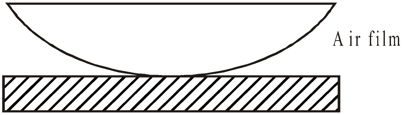
NEWTON'S RINGS
Newton observed the formation of interference rings when a plano-convex lens is placed on a plane glass plate. When viewed with white light, the fringes are coloured while with monochromatic light, the fringes are bright and dark. These fringes are produced due to interference between the light reflected from the lower surface of the lens and the upper surface of the glass plate. Interference can also take place due to transmitted light.
NEWTON'S RINGS BY REFLECTED LIGHT
Here, interference takes place due to reflected light. Therefore,
for bright rings, ......
for dark rings , ......

Proceeding further, we get the radius of rings as follows:
for bright rings, 
for dark rings, 
where R = radius of curvature of lens.
where R = radius of curvature of lens.
Note:-
- The centre is dark and alternately dark and bright rings are produced.
- While counting the order of the dark rings 1, 2, 3, etc. the central ring is not counted. Therefore,
for 1st dark ring, n = 1 and 
for 2nd dark ring, n = 2 and 
NEWTON'S RINGS BY TRANSMITTED LIGHT
Here, interference takes place due to transmitted light.

Therefore,
for bright rings, 
for dark rings, 
Proceeding further, we get
Radius of bright ring, 
Note:-
- The centre is bright and alternately bright and dark rings are obtained.
- The ring pattern due to reflected light is just opposite to that of transmitted light.
KEEP IN MEMORY
- If Dn and Dn + m be the diameters of n th and (n + m)th dark rings then the wavelength of light used is given by
where, R is the radius of curvature of the lens.
- If Dn = diameter of nth dark ring when air is present between the glass plate and the lens
Dn+m =diameter of (n+m)th dark ring when air is present between the glass plate and the lens
D′n = diameter of n th dark ring when a liquid is poured between the plate and the lens
D′n+m = diameter of (n+m)th dark ring when a liquid is poured between the plate and the lens
Then the refractive index of the liquid is given by
DIFFRACTION
When a wave is obstructed by an obstacle, the rays bend round the corner. This phenomenon is known as diffraction.
FRAUNHOFER DIFFRACTION BY SINGLE SLIT
In Fraunhofer diffraction experiment, the source and the screen are effectively at infinite distance from the diffracting element.
In single slit diffraction, imagine aperture to be divided into two equal halves. Secondary sources in these two halves give first minima at b sin θ = λ

In general, b sin θ = nλ for minima and,  for maxima.
- The points of the maximum intensity lie nearly midway between the successive minima. The amplitude E0' of the electric field at a general point P is
E0 = amplitude at the point P0 i.e. at θ = 0
The intensity at a general point P is given as 
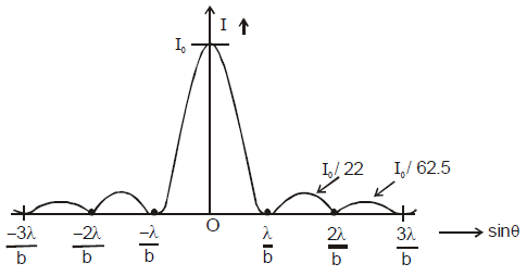
- The graph for the variation of intensity as a function of sinθ is as follows :
- The width of the central maxima is
and angular width of central maxima is
.
FRAUNHOFER DIFFRACTION BY A CIRCULAR APERTURE
- The 1st dark ring is formed by the light diffracted from the circular aperture at an angle θ with the axis where
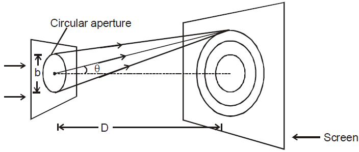
- If the screen is at a distance D (D >> b) from the circular aperture, the radius of the 1st dark ring is,
- If the light transmitted by the hole is converged by a converging lens at the screen placed at the focal plane of the lens, the radius of the 1st dark ring is
This radius is also called the radius of diffraction disc.
For plane transmission diffraction grating
(a + b) sin θn = nλ for maxima, where a = width of transparent portion, b = width of opaque portion.
DIFFERENCE BETWEEN INTERFERENCE AND DIFFRACTION OF LIGHT

POLARISATION
An ordinary source such as bulb consists of a large number of waves emitted by atoms or molecules in all directions symmetrically. Such light is called unpolarized light (see fig - a)


If we confine the direction of wave vibration of electric vector in one direction perpendicular to direction of wave propagation, then such type of light is called plane polarised or linearly polarised (with the help of polaroids or Nicol prism). The phenomenon by which, we restrict the vibrations of wave in a particular direction (see fig-b) ⊥ to direction of wave propagation is called polarization.
The plane of vibration is that which contains the vibrations of electric vector and plane of polarisation is perpendicular to the plane of vibration
Tourmaline and calcite polarises an e.m. wave passing through it.
POLARIZATION BY REFLECTION (BREWSTER’S LAW)
During reflection of a wave, we obtain a particular angle called angle of polarisation, for which the reflected light is completely plane polarised.

μ = tan (ip)
where, ip = angle of incidence, such that the reflected and refracted waves are perpendicular to each other.
LAW OF MALUS
If the electric vector is at angle θ with the transmission axis, light is partially transmitted. The intensity of transmitted light is
I = I0 cos2θ where I0 is the intensity when the incident electric vector is parallel to the transmission axis.
Polarization can also be achieved by scattering of light
- Plane polarized : oscillating electric field is in a single plane.
- Circularly polarized : tip of oscillating electric field describes a circle.
- Elliptically polarized : tip of oscillating electric field describes an ellipse.
RESOLVING POWER OF AN OPTICAL INSTRUMENT
The resolving power of an optical instrument, is its ability to distinguish between two closely spaced objects.
Diffraction occurs when light passes through the circular, or nearly circular, openings that admit light into cameras, telescopes, microscopes, and human eyes. The resulting diffraction pattern places a natural limit on the resolving power of these instruments.
For example, for normal vision, the limit of resolution of normal human eye is ~0.1 mm from 25 cm. (i.e., distances less than 0.1 mm cannot be resolved). For optical microscope the limit of resolution ~ 10–5 cm and for electron microscope ~5 Å or less.
The limit of resolution of a microscope  where a is the aperture of the microscope.
DOPPLER’S EFFECT FOR LIGHT WAVES
When the source moves towards the stationary observer or the observer moves towards the source, the apparent frequency.
When the source moves away from the stationary observer or vice-versa, the apparent frequency

where ν´ = apparent frequency, ν = active frequency
v = velocity of source, c = velocity of light
But in both cases, the relative velocity v is small.
Study Notes for JEE Main/JEE Advanced


Study Notes for NEET/AIIMS


